OVERVIEW:
Frame construction is used throughout the aerospace industry in the creation of welded steel-tube fuselages, piston-engine motor mounts, ribs, and landing gear. In this activity I design a frame assembly for a motor mount structure for a Lycoming O-300 to be installed in a light aircraft.
Equipment:
Computer with Autodesk® Inventor® installed and access to the internet.
Constraints:
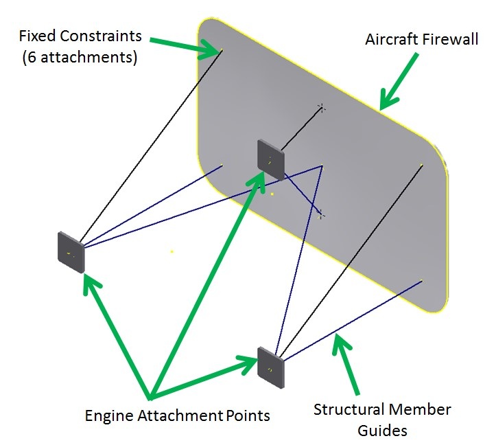
- The large plate represents the aircraft firewall as shown in the image below. This must be grounded as the stable part of the frame. Use fixed constraints on the six firewall to structural member attachment point.
- The structure will support one Lycoming O-300 engine (250 lb) attached at the three points indicated.
- The structure will be loaded with negative 3 G and positive 6 G which is simulated by exaggerated engine weight.
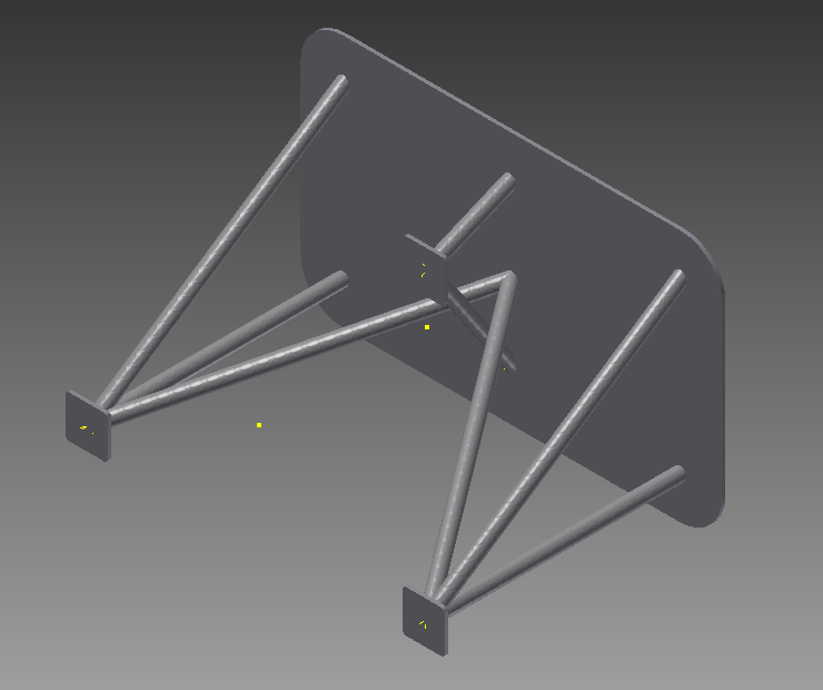
- The structural members will be 1 ½ in. ANSI pipe.
- Frame members should be mitered as necessary
I calculated the forces that must be simulated with the positive and negative G loads. I labeled the frames below with the forces that will be modeled for each loading condition. I also labeled the structural members below as compression or tension. I predict where the critical point will be for each loading condition.
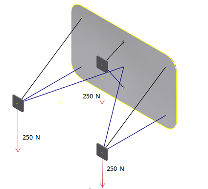
-3G
|
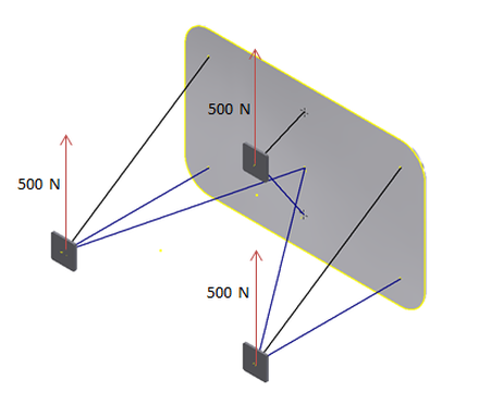
+6G
|
engine mount:
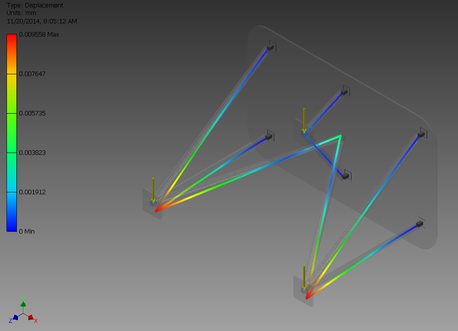
Engine mount Frame Analysis: (-3G)
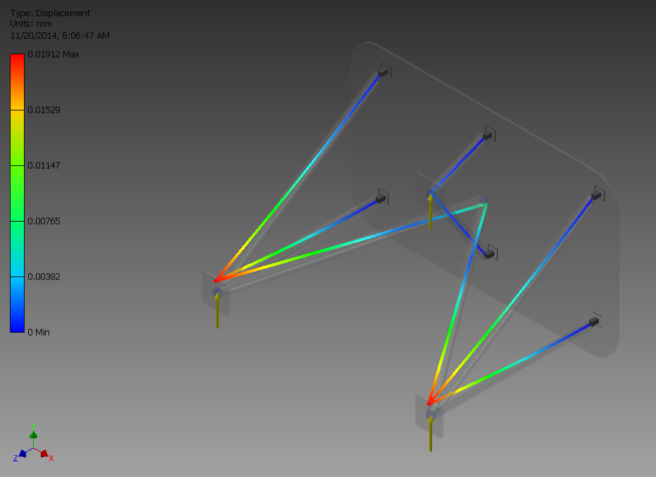
Engine Mount Frame Analysis: (+6g)
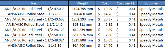
Weight and cost of materials needed to produce the frame design:
Design Benefits:
What makes my design different is my choice of materials. I used welded mild steel.
Conclusion:
1. I was expecting one of the fixed constraints to break, but the frame analysis proved me wrong.
2. An aircraft designer should include more forces to test. This simulation only tested the pitch.
2. An aircraft designer should include more forces to test. This simulation only tested the pitch.
